Tutorial
Microcontroller 8051 |
||||||
|
Using only 7 bits presents a slight problem for the left/right (L/R) mode. I want to continue using the direct duty value input, but I'll need to know when to change directions. I handled this by using the direction bit as the 8th data input. When in L/R mode, bit P1.7 is used to determine this. So, the input value 0-127 will be CCW full speed (0) to stop (127). Values 128-255 will be CW stop to full speed. In actual usage, I'll truncate the values to operate from 0-100 on each side of center (I'll explain this later).
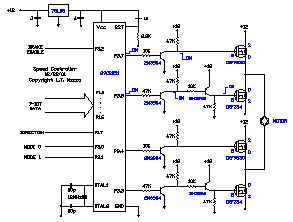
Even so, using standard FETs meant that the system was current limited due to the p-channel devices. Because of the smaller active area in the p-FET, it can't handle as much current as an n-FET. I could have used four n-channel FETs. In order to do that, I would need to generate a high voltage gate pulse for the high side switches, but I didn't want to do that. Instead, to control the motor,
I turn on the p-FET and do all the chopping with the n-FET. This doesn't
increase the current capacity of the p-FETs, but not switching them
does reduce the temperature increase that would be caused by the transition
from off to on and back off. The Firmware
As noted previously, the n-channel FETs can handle more current, and thus can handle more heat. Every time you turn a device on and off, heat is generated as the gate voltage slews from 0 to Vgate and back to 0. The steeper the slope, the less heat is generated, but nothing is instantaneous. Doing the chopping with the n-FET allows the circuit to handle larger motors. The motor I used for development draws 1 amp, and I was able to run it without any heat sinks -- the FETs didn't even get warm. Here's the code. When the program starts, it sets the stack, configures the ports and starts the interrupt timer. It then goes into a continuous loop. The first thing it does is inputs the data from Port 1. The direction bit is ANDed out and the data is compared to 0 to see if the motor should stop. If so, it goes to the stop: routine to turn off the motor drivers and see if the brake enable bit is set. If it is, it calls the brake: routine that turns on both n-FETS, effectively shorting out the motor. If the data is not 0, the mode0 bit is checked to see if the controller is in left/right mode, or not. If not, it checks the direction bit to see which pair of FETs to turn on, and jumps to the motor_on: loop. Once there, it wastes some time and counts down the value that's in the accumulator. The NOPs are there to create a 10 usec delay for each unit of the speed value. After the value reaches 0, it falls out of the loop, turns off both n-FETs (the p-FET remains on) and enters motor_chop: where it waits for the timer to interrupt and start the cycle all over again. For left/right mode, it again checks the direction bit, but for this mode, it is really the eighth bit of the speed value. For values of 80h and above, the motor is considered in forward mode, so it jumps to the go_foward: routine where it acts just like the regular direction mode. However, if the value is less than 80h, the motor goes in the reverse direction. Since I don't want the motor to start at max speed at 7Fh, I compliment the accumulator first. This makes a value of 0 the high speed. Notice that I used HEX values to explain the left/right mode. This was done to make the principle easier to understand. If you recall, I want to be able to input a decimal value between 0 and 100 to get direct duty cycle. Seven bits gives me 128 steps, but I just use 0-100 for the control input. Values 100-127 are considered the same. In fact, I had a little problem with the actual full speed value. There is quite a bit of overhead required to make the calculations, so when I got to 96% duty, the program overshot the interrupt. This made the system go to 50% duty. I tried to trim the calculations as much as possible, but in the end, I simply forced an "on full" if the value is 95% or greater. I could have reduced this error to about half by increasing the microcontroller clock to 24 MHz, and really working at the code, but this wasn't an issue with me, so I left it. I ran out of time for this issue, but next time I hope to have the R/C interface added to the controller.
|
Lesson 1: Lesson 2: |
|||||

