Tutorial
Microcontroller 8051 |
|||||||||||||||||||||||||||||||||||||||||||||||||||||||||||||||||||||||||||||||||||||||||||
|
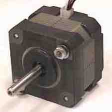
2.7. Driving
Stepper Motor Figure 2.7.1 Motor Stepper The drawing on the bottom shows power applied to the N electromagnet, drawing the compass toward it. On the right, power is instead applied to the E electromagnet, and the needle has rotated toward that side.
Just four electromagnets would give coarse jumpy motion. Now imagine a similar arrangement with 100 electromagnets around the compass. By energizing each electromagnet in sequence, the needle takes 100 steps around the circle. But driving 100 individual electromagnets would require complex electronics. We fake it:
In these drawing, the circled letters represent electromagnets. All the magnets with the same letter are wired together. When you energize that circuit, all of the electromagnets torn on at once. On the left, there are 8 magnets, but only 4 circuits. Sequencing through the four circuits gives half of a rotation. One more run through the sequence completes the rotation. This setup requires that both ends of the compass needle be north-seeking. On the right, the same 4 circuits energize 16 magnets. This setup requires 16 steps (4 repetitions of a 4-step cycle) to complete one rotation. On the right, the same 4 circuits energize 16 magnets. This setup requires 16 steps (4 repetitions of a 4-step cycle) to complete one rotation. In actual practice, just four control wires can provide just about as many steps as you might want. One of the characteristics of a given stepper motor is the number of steps necessary to make a complete circle, usually expressed as number of degrees per step. Table 2.7.1. Full Step Mode
More Complex Drive
Figure 2.7.4. Half step mode Table 2.7.2. Half Step Mode
|
Lesson 1: Lesson 2: |
||||||||||||||||||||||||||||||||||||||||||||||||||||||||||||||||||||||||||||||||||||||||||