Tutorial
Microcontroller 8051 |
||||||
|
A Microcontroller
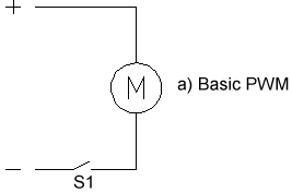
Based Motor Speed Control Motor speed control is nothing new, and I won't spend much time on it. In the basic Pulse Width Modulation (PWM) method, a switch is turned on and off to modulate the current to the motor. The ratio of "on" time to "off" time is what determines the speed of the motor. As an example, if the switch is on for 1 ms and off for 9ms, the ratio is 1 out of 10, or 10%. Another way to express this is having a duty cycle of 10%. There are many IC chips available that will do this. And if you do a search on the internet, you are bound to find some discrete circuits that will work as well.
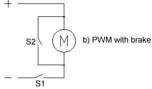
In addition to the basic PWM, you can put a switch across the motor to function as a brake (Fig. b). After the power is turned off, S2 is closed, and the motor quickly stops.
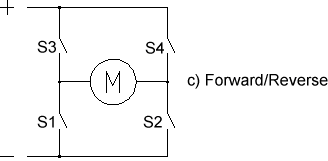
But these two methods only allow the motor to go in one direction, as it did with the R/C speed controller that I built before. If you want to run a motor both forward and reverse, you need to set up a circuit that allows you to reverse the polarity of the motor (Fig. c). This is called an H bridge.
As you can see, if you close
switches S3 and S2, the motor will spin in one direction, and if you
modulate one of these switches, you can control its speed. If you close
switches S4 and S1, the motor will spin in the other direction, and
you can control the speed by modulating one of these switches. Also
note that in this configuration, you can close switches S1 and S2 to
create a brake as we did in the circuit above. While I'm at it, it would be nice to include an interface from an R/C receiver, but that's the subject of next quarter's issue. To do all this, I'll need four outputs to control the motor FETs, one bit for the brake enable, one for the direction, and two bits to determine the mode of the controller (one direction, left/right or R/C). That leaves me 7 bits for the input data if I decide to use an 89C2051. With 7 bits I could input the HEX equivalent of 0-100 to get the direct duty cycle required. I chose HEX rather than BCD because I don't have enough I/O available with this processor. I figured that for the most part, the inputs would be coming from the parallel port of a computer or another processor, so all my output data could be in decimal form anyway. As an example, I might program my PC to output a 65d (decimal) for 65% duty. Since computers think in binary, it will convert that and output a 41h, or 1000001b. If you wish to use BCD, you will need to go to a u-controller with more inputs.
|
Lesson 1: Lesson 2: |
|||||


