| |
|
BACK
NEXT
Mini Temperature
Control and PC Monitoring trough Serial RS232
by: Tim Johnson
General Information
The TempRat is going to be a little device to switch things off if the
ambient temperature rises above a definable level. A certain time before
switching off, a message is sent down the serial link to the host computer
telling it how long until the power will be switched off. The TempRat
will then switch things back on once it thinks the temperature has gone
back to normal. The TempRat displays the ambient temperature on a 2
digit display, and also sends the temperature down the serial link once
a minute for a c omputer to log or monitor. All critical temperatures
and time delays are settable, and stored in EEPROM in case the power
fails. The TempRat has an operating temperature range of 0 degrees to
70 degrees.
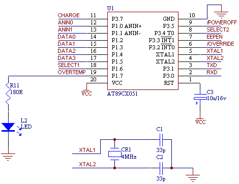
The MicroController used in the circuit is an
ATMEL 89C2051. This micro has:
2Kb of reprogrammable Flash Memory
128 x 8bit RAM
15 I/O lines
Two 16 bit timer/counters
6 interrupt sources
Programmabe serial UART, and an
On chip analog comparator
Temperature Sensing
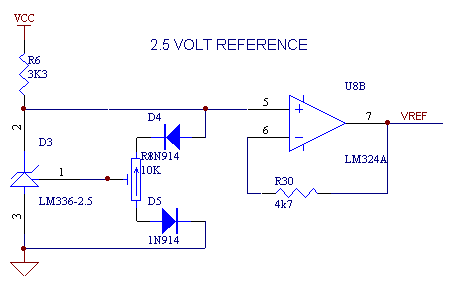
The temperature sensing in the TempRat is done using an LM334Z. This
is little device that outputs the current temperature in volts, with
10mV per degree Kelvin. This means that at 0 degrees centigrade, the
device will be showing about 2.73 volt s. This voltage is then compared
to the reference voltage (2.5 volts from an LM335-2.5) and amplified
through a differential amplifier with a differential gain of about 220/47
= 4.69. This gives, from an input voltage swing of between 2.73V and
3.43V, a (thoeretical) output voltage swing of from 1.07V to 4.35V,
working out to a 46.9mV per degree (which is a lot easier to measure,
than 10mV/deg). These things can be seen in the schematic sections below...

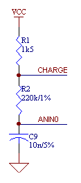
In order to save on components,
instead of putting in an ADC, the analogue comparator in the microcontroller
is used to determine the voltage. This is done by charging up a known
(fairly accurate) capacitor an d determinign how long it takes while
discharging to get to the same voltage as the sensor.
The time is measured accureately by using one of the timers in the processor.
Of course this equation for the time is an exponential one and the function
would probably use up all the code space available (only got 2k!), so
I have not put the equation in the code, but used a lookup table instead.
BACK
NEXT
|
|
Lesson 1:
T
o o l
1.1. Programmer
1.2. Edsim
51
1.3. MIDE-51
1.4. ATMEL
ISP
Lesson 2:
Input Output
2.1.LED
2.2.Swicht
2.3.7
Segmen
2.4.LCD
Character
2.5.ADC
2.6.DAC
2.7.Motor
Stepper
2.8.Keypad
Lesson 3:
Timer Counter
3.1.Basic
3.2.Mode
0
3.3.Mode
1
3.4.Mode
2
3.5.Mode
3
Lesson 4:
Serial Comm.
4.1.Basic
4.2.LED
4.3.Rotate
LED
4.2 ADC
4.3.LCD
Lesson 5:
Interuption
5.1.Basic
5.2.Timer
5.2.External
|